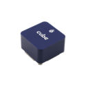
- An STM32F427 Rev 3 Flight management unit. (where the flight controller lives.)
- An STM32F100 I/O processor with pass through capabilities for failsafe. (deals with the Receiver and outputs )
- 3 IMU’s
- 1 Fixed 10 Axis IMU on the main Main board.
- (MPU9250 3 axis Accell, 3 axis gyro, and 3 axis mag, MS5611 Barometer)
- 2 Vibration Isolated and heat controlled 9DOF IMU’s and an isolated Baro.
The Cube
- (MPU9250 3 axis Accell, 3 axis gyro, and 3 axis mag, LSM303D 3 axis Accelerometer, 3Axis Magnatometer, L3GD20 3 Axis GyroMS5611 Barometer
- In case you missed it…. 3 IMU’s STANDARD.
All connections are via an 80 pin DF17 connector on the base. The following connections are included:
- 2x CAN (pins reserved for a 3rd Can bus on next years model)
- 2x I2C
- 5x Serial (1 reserved for debug)
- 2x SWD debug ports
- 2x Power input V+I
- 1x Analogue input (one of the power inputs can be used as Analogue if you need)
- Buzzer raw pwm
- Safety switch
- 8 x I/O connected PWM out (Solder option for 3.3 or 5v levels, default 3.3)(opto drive capable 10mA each)
- 6 x Aux FMU connected I/O (PWM or alternate function)
- Servo rail I/O backup power (10.5v Max)
- 2x 5.4v power in pins.

